
In most small devices, the tubing does not get to choose its own size. Something it passes through sets the outer diameter, and something that passes through it sets the inner one. What that does to a micro tubing specification, from a precision micro extrusion team that has been in Jaffrey, NH for over 50 years.
Most micro tubing is sized by its neighbors
In a larger device, outer diameter is a design decision with some give in it. If the performance justifies it, the tube can often be argued up a fraction of a French size.
Small devices rarely have that option, because the tube is usually one part of a nested set. It has to pass through something: a guide catheter, a sheath, the needle used to place it, an endoscope’s working channel, or a surgical port. The inner diameter of that part caps the tube’s outer diameter. Something also has to pass through the tube: a guidewire, an optical fiber, a smaller catheter, a coil, or a fluid. That sets a floor under its inner diameter.
A few common cases. A microcatheter for distal access has to fit inside a guide or intermediate catheter and track over a guidewire that is usually 356 microns (0.014 inch). An ophthalmic instrument sized for 25 or 27 gauge entry has an outer diameter of roughly 500 or 400 microns. A catheter placed through a needle has an outer diameter set by the needle’s bore, and the needle was chosen for the patient, not for the tubing.
In each case, two of the three numbers on the tubing print were decided before the tubing was designed. The wall is whatever is left between them, and every other requirement has to be delivered inside it: column strength, kink resistance, burst pressure, a surface that slides against the part inside, and a surface that behaves against whatever is outside.
Part 1 of Before the Spec Locks explained why OD, ID, and wall are one geometry rather than three decisions. This article is about what happens when other parts make two of those decisions for you.
Clearance is a budget, and every tolerance spends it
Nested parts need clearance between them. Too little, and the tube drags or binds inside the outer part, and the force needed to advance it climbs. Too much, and the tube has room to buckle inside the outer part instead of transmitting push, and flush or aspiration finds a path around it.
The working clearance is a small number, and every part in the stack spends some of it on tolerance. Suppose the outer part’s inner diameter can vary by plus or minus 10 microns, and so can the tube’s outer diameter. To guarantee 20 microns of diametral clearance in the worst case, the nominal clearance has to be 40 microns. Half of the gap on the drawing exists only to absorb tolerance.
The tube in the middle pays this twice: once at its outer surface, and once at its inner surface, where the guidewire or fiber has a tolerance of its own. And because the outer limit and the inner limit are both fixed, the tube’s own tolerances come out of its wall. Put plus or minus 10 microns on the OD and on the ID, and the nominal OD has to sit 10 microns under its limit while the nominal ID sits 10 microns over its own. The nominal wall loses 10 microns. If the space between the two limits allowed a 60 micron wall, the tolerances have already taken it to 50.
In a free-standing tube, a looser tolerance makes the part easier to make. In a nested tube, it makes the nominal wall thinner. That is why a nested design depends so heavily on how precisely the extruder can hold both diameters.
Where the uncertainty ends up
When a supplier cannot hold a wall precisely, the usual remedy is to add wall to cover the variation. In an unconstrained tube that extra wall goes to the outer diameter, and nobody notices. In nested micro tubing the outer diameter has nowhere to go, so the extra wall comes out of the lumen.
A smaller lumen costs more than its size suggests. If the tube carries a guidewire, an ID that drifts toward the wire shows up as friction during the procedure. If the tube carries fluid, the penalty is steeper: flow resistance through a small lumen rises with the fourth power of the radius, so giving up ten percent of the radius costs roughly a third of the flow at the same pressure. At these sizes, ten percent of the radius can be a handful of microns.
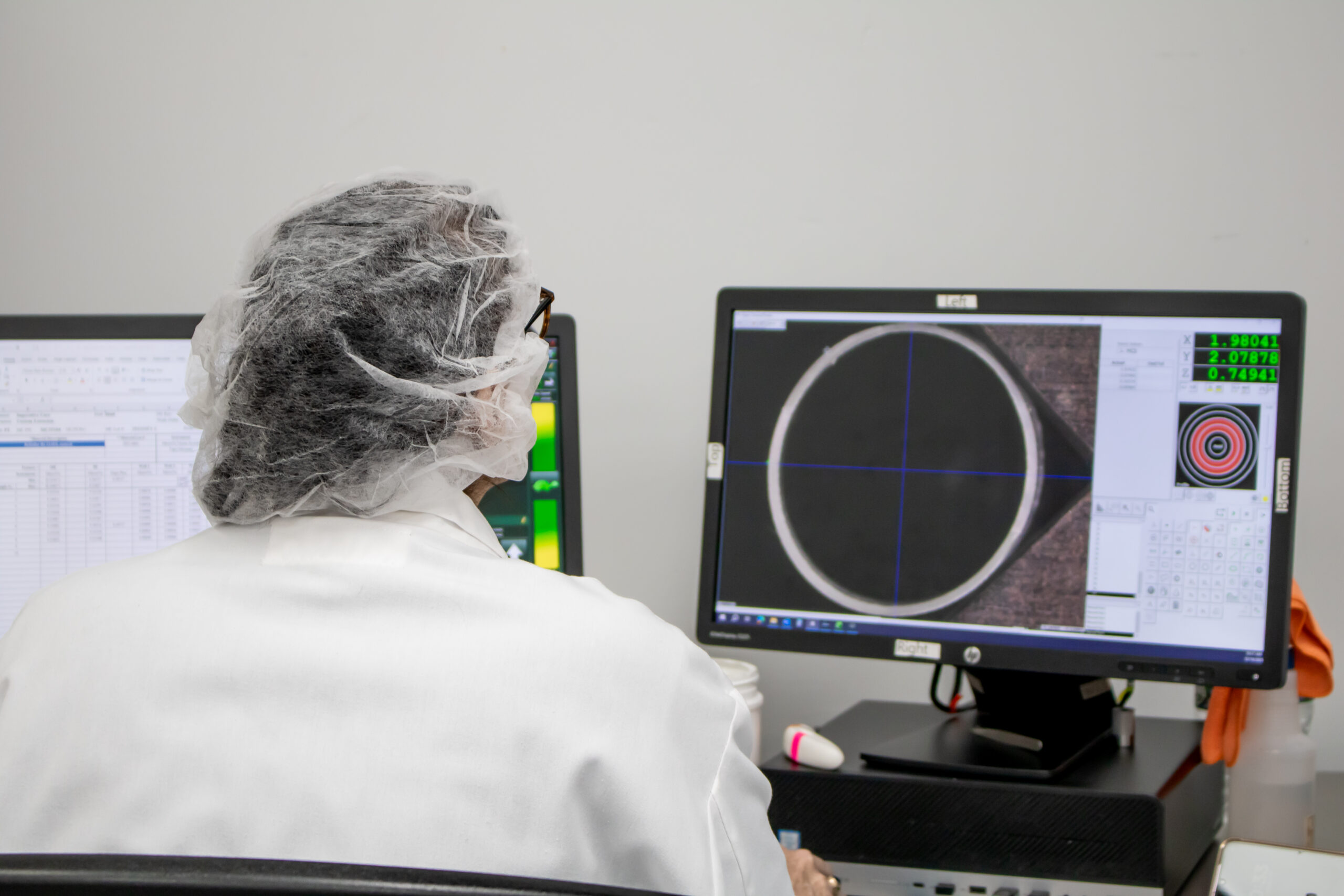
The thinnest point of the wall also matters more than the average. A lumen that sits off center leaves one side thinner than nominal, and in a wall the stack has already reduced, that side is where kinking and burst start. Concentricity deserves its own tolerance on any micro tubing print. On a nested one there is less margin to absorb it.
Asking more of a wall you cannot thicken
When the wall cannot grow, there are three ways left to change what it does: the material, the layer construction, and the process.
Material is the most direct. A higher modulus polymer can deliver the same column strength in less wall. The gain in push usually comes with a loss of flexibility, which has to be checked against the path the device takes.
Layer construction matters more in a nested tube than in most others, because its two surfaces have different neighbors. The inner surface touches the guidewire, fiber, or device inside it, so friction is the property that matters there. The outer surface touches the outer device or the tissue, so it may need to slide, to bond, or to be soft. A multilayer wall lets each surface be made from the material its neighbor needs. The cost is that every layer’s thickness comes out of the same fixed wall, so each layer has to be held as consistently as the total.
Process is the least visible of the three. Draw and cooling conditions change molecular orientation, which moves tensile strength up or down at the expense of elongation without changing a single dimension on the print. When the dimensions are already committed, that is often where the remaining design freedom is.
Questions worth asking before a nested print locks
- Which diameters are set by a neighboring part or by the anatomy, and which are we treating as fixed out of habit?
- What is the minimum clearance on each side of the tube, and has every part’s tolerance been counted against it?
- Is the nominal wall on the print what is left after the tolerances, or what was drawn before them?
- If the wall cannot grow, are we prepared to change material, layers, or process to get the behavior we need?
- Has the stack been checked with parts from more than one lot of each component?
What we bring to micro tubing this small
We are a precision micro extrusion house, and tight-clearance micro tubing that has to fit between other parts is the kind of work we are set up for.
Single, double, and triple layer construction. Ultra-soft through rigid polymers. Tolerances measured in microns and held lot after lot, so the clearance you designed is the clearance you get. Every order ships with our MC Q-Pack, containing inspection data, certification, and full material traceability. Our quality management system is ISO 13485 certified.
If you are working out a clearance stack, send us the dimensions of the parts on either side along with the tubing print. The tube in the middle is easier to design when we can see what surrounds it.